PART 2
Design_Environments
Design_environments
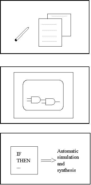
- VHDL is a tool for advancing design process
Design_environments
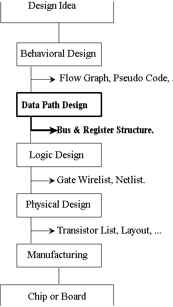
- Steps required for transforming design idea into hardware
- Each step has its representation format
Design_environments
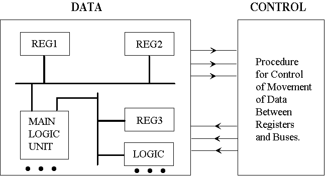
- A possible representation of data path information
- Next step is to transform into gates
Design_environments
Design entry
Simulation
Synthesis
Test generation
- Design automation helps transforming one format to another
- HDLs provide uniforms data formats
Design_environments.HDLs
Behavioral
Describes System Behavioral
Dataflow
Describes System at Register and Bus Level
Structural
Describes System at Component Level
- HDLs at various levels help different design steps
- Behavioral, Dataflow and Structural
Design_environments.HDLs
mark1 :=
BEGIN
m[0:8191]<31:0>,
pi\present.instruction<15:0>,
f\function<0:2> := pi<15:13>,
s<0:12> := pi<12:0>,
cr\control.register<12:0>,
acc\accumulator<31:0>,
- instruction.execution ** {tc}
MAIN i.cycle :=
BEGIN
pi = m[cr]<15:0> NEXT
DECODE f =>
BEGIN
0\jmp := cr = m[s],
1\jrp := cr = cr + m[s],
2\ldn := acc = - m[s],
3\sto := m[s] = acc,
4:5\sub := acc = acc - m[s],
6\cmp := IF acc LSS 0 => cr = cr + 1,
7\stp := STOP(),
END NEXT
cr = cr + 1 NEXT
RESTART i.cycle
END
- ISPS an early behavioral HDL
- Description shows MARK1 CPU
- Clocking is not explicitly specified
- High degree of readability
Design_environments.HDLs
- AHPLMODEL: multiplier.
- MEMORY: ac1[4]; ac2[4]; count[2]; extra[4]; busy.
- EXINPUTS: dataready.
- EXBUSES: inputbus[8].
- OUTPUTS: result[8]; done.
- CLUNITS: INC[2](count); ADD[5](extra; ac2);
- 1 ac1 <= inputbus[0:3]; ac2 <= inputbus[4:7];
- extra <= 4$0;
- => (~ ^dataready)/(1).
- 2 busy <= \1\;
- => (~ ^ac1[3])/(4).
- 3 extra <= ADD[1:4](extra; ac2).
- 4 extra, ac1 <= \0\, extra, ac1[0:2];
- count <= INC(count);
- => (^(&/count))/(2).
- 5 result = extra, ac1; done = \1\; busy <= \0\;
- => (1).
- END SEQUENCE
- CONTROLLERS(1).
- END.
- AHPL, A Hardware Programming Language
- Description shows an add_shift serial multiplier
- Clocking is explicitly specified
- Gate level timing is not known from this description
Design_environments.HDLs
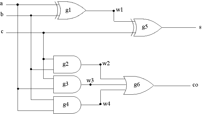
- Another level of abstraction is at the structural level
- Interconnection of components is specified
Design_environments.HDLs
- CCT full_adder (a, b, c, s, co)
- XOR (RISE = 16, FALL = 12)
- g1 (w1, a, b),
- g2 (s, w1, c);
- AND (RISE4 = 12, FALL = 10)
- g2 (w2, c, b),
- g3 (w3, c, a),
- g4 (w4, b, a);
- OR (RISE = 12, FALL = 10)
- g6 (co, w2, w3, w4);
- INPUT a, b, c;
- WIRE w1, w2, w3, w4;
- OUTPUT s, co;
- END CIRCUIT full_adder
- Full adder of previous slide is described in GHDL
- Complete timing at gate level is known by this description
- Hard to extract functionality by reading the description
Design_environments.tools
Simulation:
Describe system and operation
Synthesis:
Describe system and automatically generate hardware
- Simulation and synthesis are two main HDL based tool
- Can simulate and synthesize with any level of abstraction
Design_environments.tools. simulation
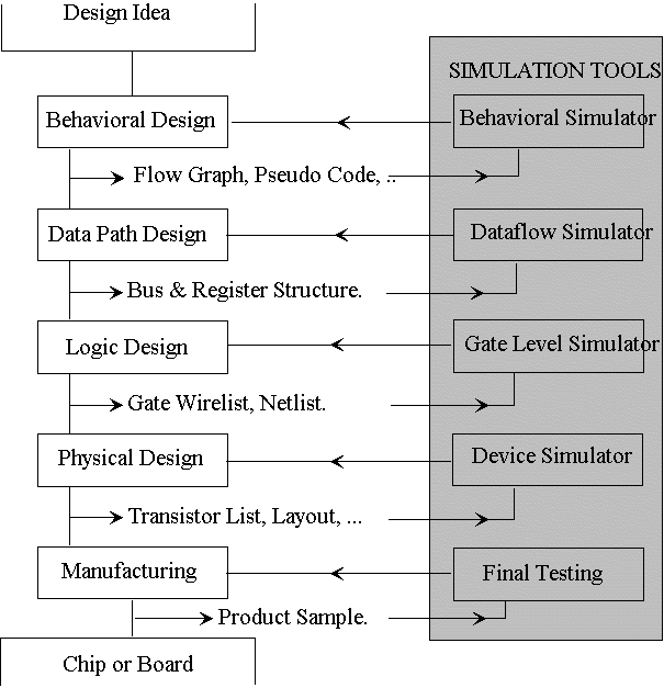
- Simulation tools verify transformation at each step
- Verify each step before going to next
Design_environments.tools. simulation


- Oblivious and event driven simulation
- Can simulate gate level circuit with both methods
Design_environments.tools. simulation
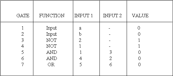
- Need a tabular netlist for oblivious simulation
- Simulate a fixed time invervals
- Update table values at each interval
Design_environments.tools. simulation
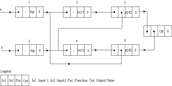
- Event driven simulation requires a linked list data structure
- Evaluate circuit only when events occur
- Offers a faster simulation for digital systems


