PART 4
General CPU description
- General.CPU_description.the_CPU
- PARWAN; PAR_1; A Reduced Processor
- Simple 8-bit CPU
- 8-bit Data; 12-bit Address
- Primarily designed for educational purposes
- Includes most common instructions
- General.CPU_description.memory_organization

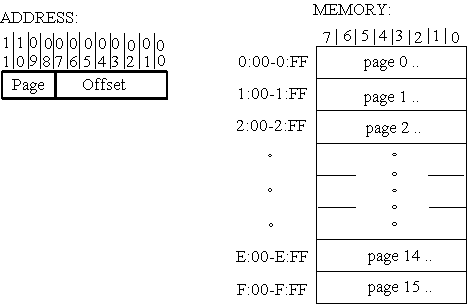
- Memory divided into pages
- Pages of 256 bytes
- Address has page and offset part
- Uses memory mapped IO
- General.CPU_description.instructions
- FULL Address; (12 bits) direct/indirect
- LDA, AND, ADD, SUB, JMP, STA
- PAGE Address, (8 bit)
- JSR, BRA_V, BRA_C, BRA_Z, BRA_N
- NO Address
- NOP, CLA, CMA, CMC, ASL, ASR
- Three groups of instructions
- Full Address instructions include page and offset
- Page address instructions include offset
- No Address instructions occupy a single byte
- General.CPU_description.instructions

- Load and store operations
- Arithmetic & logical operations
- jmp and branch instructions
- General.CPU_description.instructions
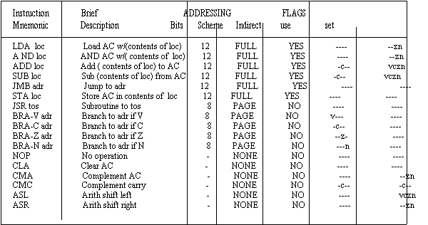
- CPU contains V C Z N flags
- Instructions use and/or influence these flags
- General.CPU_description.instructions

- Arithmetic instructions influence all flags
- Branch instructions use corresponding flags
- Shift instructions influence all flags
- General.CPU_description.addressing
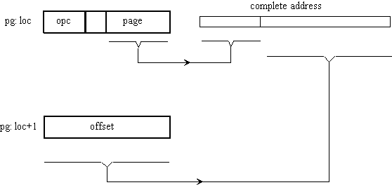
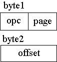
- Full address instructions use two bytes
- Right hand side of first byte is page
- Second byte contains offset
- Bit 4 is direct/indirect indicator
- General.CPU_description.addressing
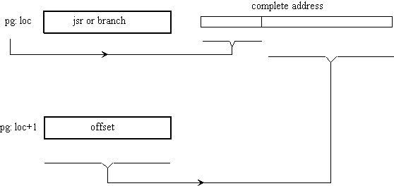
- Page address instructions use two bytes
- All of first byte is used by opcode
- Page part of address uses current page
- Second byte is the offset
- General.CPU_description.addressing

- BRANCH TO 6A if carry is set
- c=0 : Next instruction from 5:0f
- c=1 : Next instruction from 5:6A
- Branching is done within current page only
- General.CPU_description.addressing
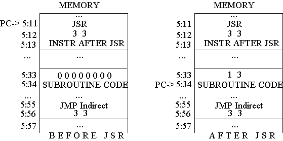
- Store jsr return address at tos
- Begin subroutine at tos+1
- Use indirect jmp to tos for return from subroutine
- General.CPU_description.addressing

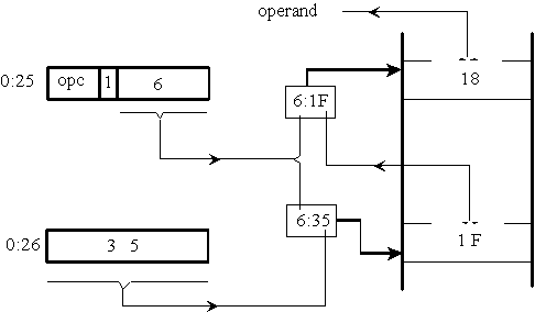
- Indirect addressing effects offset only
- To obtain actual address full addressing is used
- To obtain data page addressing is used
- General.CPU_description.coding
- 0:15 cla -- clear accumulator
- 0:16 asl -- clears carry
- 0:17 add, i 4:00 -- add bytes
- 0:19 sta 4:03 -- store partial sum
- 0:1B lda 4:00 -- load pointer
- 0:1D add 4:02 -- increment pointer
- 0:1F sta 4:00 -- store pointer back
- 0:21 lda 4:01 -- load count
- 0:23 sub 4:02 -- decrement count
- 0:25 bra_z :2D -- end if zero count
- 0:27 sta 4:01 -- store count back
- 0:29 lda 4:03 -- get partial sum
- 0:2B jmp 0:17 -- go for next byte
- 0:2D nop -- adding completed
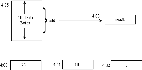
- A program to add 10 bytes
- Use location 4:00 for data pointer
- Use location 4:01 for counter
- Constant 1 in 4:02 is used for +1 and -1
- General.CPU_description.coding
- LIBRARY cmos;
- USE cmos.basic_utilities.ALL;
- --
- PACKAGE par_utilities IS
- FUNCTION "XOR" (a, b : qit) RETURN qit ;
- --
- FUNCTION "AND" (a, b : qit_vector) RETURN qit_vector;
- FUNCTION "OR" (a, b : qit_vector) RETURN qit_vector;
- FUNCTION "NOT" (a : qit_vector) RETURN qit_vector;
- --
- SUBTYPE nibble IS qit_vector (3 DOWNTO 0);
- SUBTYPE byte IS qit_vector (7 DOWNTO 0);
- SUBTYPE twelve IS qit_vector (11 DOWNTO 0);
- --
- SUBTYPE wired_nibble IS wired_qit_vector (3 DOWNTO 0);
- SUBTYPE wired_byte IS wired_qit_vector (7 DOWNTO 0);
- SUBTYPE wired_twelve IS wired_qit_vector (11 DOWNTO 0);
- --
- SUBTYPE ored_nibble IS ored_qit_vector (3 DOWNTO 0);
- SUBTYPE ored_byte IS ored_qit_vector (7 DOWNTO 0);
- SUBTYPE ored_twelve IS ored_qit_vector (11 DOWNTO 0);
- --
- CONSTANT zero_4 : nibble := "0000";
- CONSTANT zero_8 : byte := "00000000";
- CONSTANT zero_12 : twelve := "000000000000";
- --
- FUNCTION add_cv (a, b : qit_vector; cin : qit) RETURN qit_vector;
- FUNCTION sub_cv (a, b : qit_vector; cin : qit) RETURN qit_vector;
- --
- FUNCTION set_if_zero (a : qit_vector) RETURN qit;
- --
- END par_utilities;
- Machine descriptions requires utilities
- Use basic_utilities
- Additional utilities are included in par_utilities
- General.CPU_description.coding
- PACKAGE body par_utilities IS
- FUNCTION "XOR" (a, b : qit) RETURN qit IS
- CONSTANT qit_or_table : qit_2d := (
- ('0','1','1','X'),
- ('1','0','0','X'),
- ('1','0','0','X'),
- ('X','X','X','X'));
- BEGIN
- RETURN qit_or_table (a, b);
- END "XOR";
- FUNCTION "AND" (a,b : qit_vector) RETURN qit_vector IS
- VARIABLE r : qit_vector (a'RANGE);
- BEGIN
- loop1: FOR i IN a'RANGE LOOP
- r(i) := a(i) AND b(i);
- END LOOP loop1; RETURN r;
- END "AND";
- --
- FUNCTION "OR" (a,b: qit_vector) RETURN qit_vector IS
- VARIABLE r: qit_vector (a'RANGE);
- BEGIN
- loop1: FOR i IN a'RANGE LOOP
- r(i) := a(i) OR b(i);
- END LOOP loop1; RETURN r;
- END "OR";
- --
- FUNCTION "NOT" (a: qit_vector) RETURN qit_vector IS
- VARIABLE r: qit_vector (a'RANGE);
- BEGIN
- loop1: FOR i IN a'RANGE LOOP
- r(i) := NOT a(i);
- END LOOP loop1; RETURN r;
- END "NOT";
- Define XOR in qit
- Overload logical operators with qit_vector
- General.CPU_description.coding
- --
- FUNCTION add_cv (a, b : qit_vector; cin : qit) RETURN qit_vector IS
- --left bits are sign bit
- VARIABLE r, c: qit_vector (a'LEFT + 2 DOWNTO 0);
- -- two extra bits in r are: msb for overflow, next carry
- VARIABLE a_sign, b_sign: qit;
- BEGIN
- a_sign := a(a'LEFT); b_sign := b(b'LEFT);
- r(0) := a(0) XOR b(0) XOR cin;
- c(0) := ((a(0) XOR b(0)) AND cin) OR (a(0) AND b(0));
- FOR i IN 1 TO (a'LEFT) LOOP
- r(i) := a(i) XOR b(i) XOR c(i-1);
- c(i) := ((a(i) XOR b(i)) AND c(i-1)) OR (a(i) AND b(i));
- END LOOP;
- r(a'LEFT+1) := c(a'LEFT);
- IF a_sign = b_sign AND r(a'LEFT) /= a_sign
- THEN r(a'LEFT+2) := '1'; --overflow
- ELSE r(a'LEFT+2) := '0'; END IF; RETURN r;
- END add_cv;
- FUNCTION sub_cv (a, b : qit_vector; cin : qit) RETURN qit_vector IS
- VARIABLE not_b : qit_vector (b'LEFT DOWNTO 0);
- VARIABLE not_c : qit;
- VARIABLE r : qit_vector (a'LEFT + 2 DOWNTO 0);
- BEGIN
- not_b := NOT b; not_c := NOT cin;
- r := add_cv (a, not_b, not_c); RETURN r;
- END sub_cv;
- FUNCTION set_if_zero (a : qit_vector) RETURN qit IS
- VARIABLE zero : qit := '1';
- BEGIN
- FOR i IN a'RANGE LOOP
- IF a(i) /= '0' THEN zero := '0'; EXIT;
- END IF;
- END LOOP; RETURN zero;
- END set_if_zero;
- END par_utilities;
- add_cv adds its operands creates c and v bits
- Put overflow in leftmost result bit
- Put carry to the right of overflow
- General.CPU_description.coding
- LIBRARY cmos;
- USE cmos.basic_utilities.ALL;
- --
- PACKAGE par_parameters IS
- CONSTANT single_byte_instructions : qit_vector (3 DOWNTO 0) := "1110";
- CONSTANT cla : qit_vector (3 DOWNTO 0) := "0001";
- CONSTANT cma : qit_vector (3 DOWNTO 0) := "0010";
- CONSTANT cmc : qit_vector (3 DOWNTO 0) := "0100";
- CONSTANT asl : qit_vector (3 DOWNTO 0) := "1000";
- CONSTANT asr : qit_vector (3 DOWNTO 0) := "1001";
- CONSTANT jsr : qit_vector (2 DOWNTO 0) := "110";
- CONSTANT bra : qit_vector (3 DOWNTO 0) := "1111";
- CONSTANT indirect : qit := '1';
- CONSTANT jmp : qit_vector (2 DOWNTO 0) := "100";
- CONSTANT sta : qit_vector (2 DOWNTO 0) := "101";
- CONSTANT lda : qit_vector (2 DOWNTO 0) := "000";
- CONSTANT ann : qit_vector (2 DOWNTO 0) := "001";
- CONSTANT add : qit_vector (2 DOWNTO 0) := "010";
- CONSTANT sbb : qit_vector (2 DOWNTO 0) := "011";
- END par_parameters;
- Assign appropriate names to opcodes
- par_parameters is used for readability
- General.CPU_description.coding
- Libraries
- Interface
- Architecture
- Description includes Interface and Architecture
- Use a single process for machine operation
- General.CPU_description.interface
- LIBRARY cmos;
- USE cmos.basic_utilities.ALL;
- LIBRARY par_library;
- USE par_library.par_utilities.ALL;
- USE par_library.par_parameters.ALL;
- --
- ENTITY par_central_processing_unit IS
- GENERIC (read_high_time, read_low_time,
- write_high_time, write_low_time : TIME := 2 US;
- cycle_time : TIME := 4 US; run_time : TIME := 140 US);
- PORT (clk : IN qit;
- interrupt : IN qit;
- read_mem, write_mem : OUT qit;
- databus : INOUT wired_byte BUS := "ZZZZZZZZ"; adbus : OUT twelve
- );
- END par_central_processing_unit;
- Make packages visible
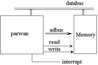
- Databus can be driven by Parwan and memory
- Use wiring resolution function
- Generic parameters specify relative read/write cycle time
- General.CPU_description.behavioral
- ARCHITECTURE behavioral OF par_central_processing_unit IS
- BEGIN
- PROCESS
- Declare necessary variables;
- BEGIN
- IF NOW > run_time THEN WAIT; END IF;
- IF interrupt = '1' THEN
- Handle interrupt;
- ELSE -- no interrupt
- Read first byte into byte1, increment pc;
- IF byte1 (7 DOWNTO 4) = single_byte_instructions THEN
- Execute single_byte instructions;
- ELSE -- two-byte instructions
- Read secound byte into byte2, increment pc;
- IF byte1 (7 DOWNTO 5) = jsr THEN
- Execute jsr instruction, byte2 has address;
- ELSIF byte1 (7 DOWNTO 4) = bra THEN
- Execute bra instructions, address in byte2;
- ELSE -- all other two-byte instructions
- IF byte1 (4) = indirect THEN
- Use byte1 and byte2 to get address;
- END IF; -- ends indirect
- IF byte1 (7 DOWNTO 5) = jmp THEN
- Execute jmp instruction,
- ELSIF byte1 (7 DOWNTO 5) = sta THEN
- Execute sta instruction, write ac;
- ELSE -- read operand for lda, and, add, sub
- Read memory onto databus ;
- Execute lda, and, add, and sub;
- Remove memory from databus;
- END IF; -- jmp / sta / lda, and, add, sub
- END IF; -- jsr / bra / other double-byte instructions
- END IF; -- single-byte / double-byte
- END IF; -- interrupt / otherwise
- END PROCESS;
- END behavioral;
- A single process describes the machine
- IF_THEN_ELSE statements separate instructions
- General.CPU_description.coding_individual_instructions
- Declare necessary variables
- VARIABLE pc : twelve;
- VARIABLE ac, byte1, byte2 : byte;
- VARIABLE v, c, z, n : qit;
- VARIABLE temp : qit_vector (9 DOWNTO 0);
- Variables store internal information
- No hardware correspondence is specified
- General.CPU_description.coding_individual_instructions
- Handle interrupt
- pc := zero_12;
- WAIT FOR cycle_time;
- Read first byte into byte1, increment pc
- adbus <= pc;
- read_mem <= '1'; WAIT FOR read_high_time;
- byte1 := byte (databus);
- read_mem <= '0'; WAIT FOR read_low_time;
- pc := inc (pc);
- Interrupt handing: reset pc, wait a clock
- To read byte:
- Put pc on address bus
- Wait half a clock cycle
- Read data bus
- Remove read request
- End fetch by incrementing pc
- General.CPU_description.coding_individual_instructions
- Execute single_byte instructions
- CASE byte1 (3 DOWNTO 0) IS
- WHEN cla =>
- ac := zero_8;
- WHEN cma =>
- ac := NOT ac;
- IF ac = zero_8 THEN z := '1'; END IF;
- n := ac (7);
- WHEN cmc =>
- c := NOT c;
- WHEN asl =>
- c := ac (7);
- ac := ac(6) & ac (5 DOWNTO 0) & '0';
- -- ac := ac (6 DOWNTO 0) & '0';
- n := ac (7);
- IF c /= n THEN v := '1'; END IF;
- WHEN asr =>
- ac := ac (7) & ac (7 DOWNTO 1);
- IF ac = zero_8 THEN z := '1'; END IF;
- n := ac (7);
- WHEN OTHERS => NULL;
- END CASE;
- Handing single_byte instructions, cla, cma, cmc, asl and asr
- Negative flag may be set for cma, asl and asr
- Zero flag may be set for cma, asl and asr
- For asl, overflow occurs it bits 6 & 7 differ
- General.CPU_description.coding_individual_instructions
- Read second byte into byte2, increment pc
- adbus <= pc;
- read_mem <= '1'; WAIT FOR read_high_time;
- byte2 := byte (databus);
- read_mem <= '0'; WAIT FOR read_low_time;
- pc := inc (pc);
- Reading byte from memory
- Read_memory stays high for half a clock
- Memory releases the bus in the second half
- Right half of byte1 has page for full address
- Byte2 now has the offset of address
- General.CPU_description.coding_individual_instructions
- Execute jsr instruction, byte2 has address
- databus <= wired_byte (pc (7 DOWNTO 0) );
- adbus (7 DOWNTO 0) <= byte2;
- write_mem <= '1'; WAIT FOR write_high_time;
- write_mem <= '0'; WAIT FOR write_low_time;
- databus <= "ZZZZZZZZ";
- pc (7 DOWNTO 0) := inc (byte2);
- Handling jsr
- Page part of adbus still points to the same instruction page
- Write pc to page location pointed by byte2
- when writing is done, release the databus
- Load pc to start from byte2+1 (tos)
- General.CPU_description.coding_individual_instructions
- Execute bra instructions, address in byte2
- IF
- ( byte1 (3) = '1' AND v = '1' ) OR
- ( byte1 (2) = '1' AND c = '1' ) OR
- ( byte1 (1) = '1' AND z = '1' ) OR
- ( byte1 (0) = '1' AND n = '1' )
- THEN
- pc (7 DOWNTO 0) := byte2;
- END IF;
- Chock bits 3, 2, 1 and 0 against v, c, z, n flags
- Load pc with byte2 if match is found
- Page part of pc still holds some page
- General.CPU_description.coding_individual_instructions
- Use byte1 and byte2 to get address
- adbus (11 DOWNTO 8) <= byte1 (3 DOWNTO 0);
- adbus (7 DOWNTO 0) <= byte2;
- read_mem <= '1'; WAIT FOR read_high_time;
- byte2 := byte (databus);
- read_mem <= '0'; WAIT FOR read_low_time;
- Use page of byte1, offset of byte2
- Form an address to fetch offset of operand
- Now byte1 & byte2 contain full operand address
- General.CPU_description.coding_individual_instructions
- Execute jmp instruction
- pc := byte1 (3 DOWNTO 0) & byte2;
- Load pc with full 12-bit address
- Could use two assignments instead of &
- General.CPU_description.coding_individual_instructions
- Execute sta instruction, write ac
- adbus <= byte1 (3 DOWNTO 0) & byte2;
- databus <= wired_byte (ac);
- write_mem <= '1'; WAIT FOR write_high_time;
- write_mem <= '0'; WAIT FOR write_low_time;
- databus <= "ZZZZZZZZ";
- Put full address on adbus
- Put ac on databus
- Issue write, when done, release databus
- General.CPU_description.coding_individual_instructions
- Read memory onto databus
- adbus (11 DOWNTO 8) <= byte1 (3 DOWNTO 0);
- adbus (7 DOWNTO 0) <= byte2;
- read_mem <= '1'; WAIT FOR read_high_time;
- CASE byte1 (7 DOWNTO 5) IS
- WHEN lda =>
- ac := byte (databus);
- WHEN ann =>
- ac := ac AND byte (databus);
- WHEN add =>
- temp := add_cv (ac, byte (databus), c);
- ac := temp (7 DOWNTO 0);
- c := temp (8);
- v := temp (9);
- WHEN sbb =>
- temp := sub_cv (ac, byte (databus), c);
- ac := temp (7 DOWNTO 0);
- c := temp (8);
- v := temp (9);
- WHEN OTHERS => NULL;
- END CASE;
- IF ac = zero_8 THEN z := '1'; END IF;
- n := ac (7);
- read_mem <= '0'; WAIT FOR read_low_time;
- Full address on adbus
- Issue read_mem
- Perform lda, ann, add and sbb
- Arithmetic operations set c and v flags
- All operations set z and n flags
General.CPU_description .complete_behavioral
- ARCHITECTURE behavioral OF par_central_processing_unit IS
- BEGIN
- PROCESS
- VARIABLE pc : twelve;
- VARIABLE ac, byte1, byte2 : byte;
- VARIABLE v, c, z, n : qit;
- VARIABLE temp : qit_vector (9 DOWNTO 0);
- VARIABLE pc : twelve;
- VARIABLE ac, byte1, byte2 : byte;
- VARIABLE v, c, z, n : qit;
- VARIABLE temp : qit_vector (9 DOWNTO 0);
- BEGIN
- IF NOW > run_time THEN WAIT; END IF;
- IF interrupt = '1' THEN
- pc := zero_12;
- WAIT FOR cycle_time;
- ELSE -- no interrupt
- adbus <= pc;
- read_mem <= '1'; WAIT FOR read_high_time;
- byte1 := byte (databus);
- read_mem <= '0'; WAIT FOR read_low_time;
- pc := inc (pc);
- IF byte1 (7 DOWNTO 4) = single_byte_instructions THEN
- CASE byte1 (3 DOWNTO 0) IS
- WHEN cla =>
- ac := zero_8;
- WHEN cma =>
- ac := NOT ac;
- IF ac = zero_8 THEN z := '1'; END IF;
- n := ac (7);
- WHEN cmc =>
- c := NOT c;
- WHEN asl =>
- c := ac (7);
- ac := ac (6 DOWNTO 0) & '0';
- n := ac (7);
- IF c /= n THEN v := '1'; END IF;
- WHEN asr =>
- ac := ac (7) & ac (7 DOWNTO 1);
- IF ac = zero_8 THEN z := '1'; END IF;
- n := ac (7);
- WHEN OTHERS => NULL;
- END CASE;
- ELSE -- two-byte instructions
- adbus <= pc;
- read_mem <= '1'; WAIT FOR read_high_time;
- byte2 := byte (databus);
- read_mem <= '0'; WAIT FOR read_low_time;
- pc := inc (pc);
- Complete behavioral description
- Part 1 of 2
General.CPU_description .complete_behavioral
- IF byte1 (7 DOWNTO 5) = jsr THEN
- databus <= wired_byte (pc (7 DOWNTO 0) );
- adbus (7 DOWNTO 0) <= byte2;
- write_mem <= '1'; WAIT FOR write_high_time;
- write_mem <= '0'; WAIT FOR write_low_time;
- databus <= "ZZZZZZZZ";
- pc (7 DOWNTO 0) := inc (byte2);
- ELSIF byte1 (7 DOWNTO 4) = bra THEN
- IF ( byte1 (3) = '1' AND v = '1' ) OR ( byte1 (2) = '1' AND c = '1' ) OR
- ( byte1 (1) = '1' AND z = '1' ) OR ( byte1 (0) = '1' AND n = '1' )
- THEN
- pc (7 DOWNTO 0) := byte2;
- END IF;
- ELSE -- all other two-byte instructions
- IF byte1 (4) = indirect THEN
- adbus (11 DOWNTO 8) <= byte1 (3 DOWNTO 0);
- adbus (7 DOWNTO 0) <= byte2;
- read_mem <= '1'; WAIT FOR read_high_time;
- byte2 := byte (databus);
- read_mem <= '0'; WAIT FOR read_low_time;
- END IF; -- ends indirect
- IF byte1 (7 DOWNTO 5) = jmp THEN
- pc := byte1 (3 DOWNTO 0) & byte2;
- ELSIF byte1 (7 DOWNTO 5) = sta THEN
- adbus <= byte1 (3 DOWNTO 0) & byte2;
- databus <= wired_byte (ac);
- write_mem <= '1'; WAIT FOR write_high_time;
- write_mem <= '0'; WAIT FOR write_low_time;
- databus <= "ZZZZZZZZ";
- ELSE -- read operand for lda, and, add, sub
- adbus (11 DOWNTO 8) <= byte1 (3 DOWNTO 0);
- adbus (7 DOWNTO 0) <= byte2;
- read_mem <= '1'; WAIT FOR read_high_time;
- CASE byte1 (7 DOWNTO 5) IS
- WHEN lda =>
- ac := byte (databus);
- WHEN ann =>
- ac := ac AND byte (databus);
- WHEN add =>
- temp := add_cv (ac, byte (databus), c);
- ac := temp (7 DOWNTO 0); c := temp (8); v := temp (9);
- WHEN sbb =>
- temp := sub_cv (ac, byte (databus), c);
- ac := temp (7 DOWNTO 0); c := temp (8); v := temp (9);
- WHEN OTHERS => NULL;
- END CASE;
- IF ac = zero_8 THEN z := '1'; END IF;
- n := ac (7);
- read_mem <= '0'; WAIT FOR read_low_time;
- END IF; -- jmp / sta / lda, and, add, sub
- END IF; -- jsr / bra / other double-byte instructions
- END IF; -- single-byte / double-byte
- END IF; -- interrupt / otherwise
- END PROCESS;
- END behavioral;
- Complete behavioral description
- part 2/2
- General. conclusions
1. Outline: Introduction, Organization, Outline
2. Review: Levels of abstraction, Entity and Architecture, Signal assignments, Guarded signal assignments, Three state bussing, Process statements, Combinational processes, Sequential processes, Multiplexing, Package
3. MSI Based Design: Use MSI parts of Part 2, Sequential multiplication, Designing the multiplier, Control and data parts, Testing the multiplier
5. Manual Data_path Design: Will present VHDL description for manual design of data_path. Data components, Bussing structure, Description of logic, Description of registers, Bus resolutions, Component wiring
6. Manual Controller Design: Will present VHDL description for manual design of controller. Controller hardware, VHDL style, Signals and resolutions, State descriptions, Complete CPU, Testing CPU
7. Synthesis: Main concepts, Structural synthesis, Combinational circuits, Functional registers, State machines
8. Behavioral_Synthesis: Will present a high level synthesizable CPU description. Synthesis style, Necessary Package, Interface, General Layout, Registers, Clocking, Sequencing, Simulation and Synthesis
9. Dataflow_Synthesis: Will partition the CPU and synthesize each part separately. Synthesis style, Controller, Data components, Data path, Synthesized example, Conclusions
to the top of the document


