PART 7
Synthesis
In general:
We will present an overview of synthesis. What is expected from present tools.
Synthesis.main_concepts
Hardware Generation
Library Mapping
Optimization
Resource sharing
Synthesis transforms one hardware format to another
Results are mapped to a certain library
Optimization reduces logic
Resources such as adders can be reused
Synthesis.main_concepts

Design process includes high level simulation
Synthesizer is used after design verification
Simulate after synthesis to verify timing
Synthesis.main_concepts
Std_logic
Integer
Enumeration types
Synthesizers support IEEE 1164 mvl9
Integer type for signals is supported
Enumeration types are used for states of state machines
No timing of type TIME is synthesized
Synthesis.main_concepts
Can synthesize
Structural
Dataflow
Behavioral
Can start with sub_component specification
Can use signal assignments
Can specify functionality in a process statement
Synthesis.main_concepts
ARCHITECTURE structural OF xnor IS
COMPONENT xor2 PORT ( i1, i2 : IN BIT; o1 : OUT BIT );
COMPONENT not1 PORT ( i1 : IN BIT; o1 : OUT BIT );
SIGNAL x : BIT;
BEGIN
c1 : xor2 PORT MAP ( i1, i2, x );
c2 : not1 PORT MAP ( x, o1 );
END structural;
At the structural level, wiring predefined parts are specified
Parts come from specific technology libraries
Synthesis.main_concepts
ARCHITECTURE dataflow OF xnor IS
BEGIN
o1 <= NOT (i1 XOR i2);
END dataflow;
Dataflow specifies bus and register transfers
Synthesizers generate hardware specified at dataflow level
Synthesis.main_concepts
ARCHITECTURE behavioral OF xnor IS
BEGIN
PROCESS ( i1, i2 )
BEGIN
IF i1 = i2 THEN
o1 <= '1';
ELSE
o1 <= '0';
END IF;
END PROCESS
END behavioral
Behavioral level is the easiest to specify hardware
Synthesizers use this level for synthesis
Certain rules must be followed
Synthesis.structural_synthesis
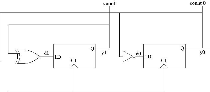
ARCHITECTURE structural OF counter2 IS
COMPONENT dff PORT(ck, data : IN BIT; q : OUT BIT);
END COMPONENT;
COMPONENT xor2 PORT (i1, i2 : IN BIT; o1 : OUT BIT);
END COMPONENT;
COMPONENT not1 PORT (i1 : IN BIT ; o1 : OUT BIT);
END COMPONENT;
SIGNAL d1, y, d0, y0 : BIT;
BEGIN
u1 : dff PORT MAP (clk, d1, y1);
u2 : dff PORT MAP (clk, d0, y0);
u3 : xor2 PORT MAP (y1, y0, d1);
u4 : not1 PORT MAP (y0, d0);
count0 <= y0;
count1 <= y1;
END structural;
Use structural to build larger components form smaller ones
Can wire full adders into n_bit adders
Hardware is generated from predefined library cells
Synthesis.structural_synthesis

Hardware generated from structural of counter2
Can use this design in larger designs
Can do other parts of design at dataflow or structural
This way you control parts to use
Some libraries may include large functional blocks
Structural synthesis allows use of functional blocks
Synthesis.combinational_circuits
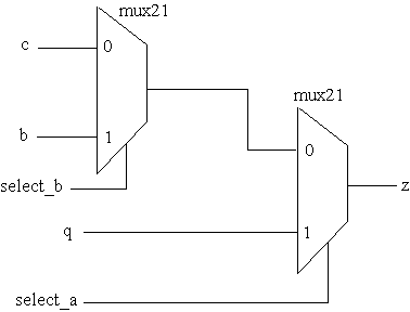
ENTITY selecting IS
PORT (a, select_a, b, select_b, c : IN std_logic; z : OUT std_logic);
END selecting;
ARCHITECTURE behavioral OF selecting IS
BEGIN
PROCESS (a, select_a, b, select_b, c)
BEGIN
IF select_a = '1' THEN
z <= a;
ELSIF select_b = '1' THEN
z <= b;
ELSE
z <= c;
END IF;
END PROCESS;
END behavioral;

A behavioral combinational process translates to a combinational circuit
Process must be sensitive to all inputs
This process does not store values
Synthesis.combinational_circuits
ARCHITECTURE dataflow OF selecting IS
BEGIN
z <= a WHEN select_a = '1' ELSE
b WHEN select_b = '1' ELSE
c;
END dataflow;
Same hardware can be generated by a dataflow description
In this description AFTER clauses are ignored by the synthesizer
Can use subprograms for logic functions
Synthesis.combinational_circuits
.
.
.
bus_a <= reg_1 WHEN put_reg_1_on_bus = '1'
ELSE "zzzz";
.
.
.
bus_a <= reg_z WHEN put_reg_z_on_bus = '1'
ELSE "zzzz";
.
.
.

Bussing can be specified by use of conditional signal assignments
Assigning "zzzz" is synthesized as opening a three_state gate
Hardware is generated by use of available library cells
Synthesis.functional_registers
ENTITY counter2 IS
PORT (clk, reset : IN std_logic;
count : BUFFER std_logic_vector ( 1 DOWNTO 0));
END counter2;
--
ARCHITECTURE behavioral OF counter2 IS
BEGIN
PROCESS
BEGIN
WAIT UNTIL ( clk'EVENT AND clk = '1' );
IF reset = '1' OR count = "11" THEN
count <= "00";
ELSE
count <= count + "01";
END IF;
END PROCESS;
END behavioral;
A WAIT in process, implies clocking
Can also use IF( clk' EVENT AND clk = '1') with sensitivity list
An edge condition must be the last of IF statement
Synthesis.functional_registers

A possible hardware generated for counter
Cells from an available library are used
Synthesis.functional_registers
ARCHITECTURE dataflow OF counter2 IS
BEGIN
bc : BLOCK ( clk'EVENT AND clk = '1' )
BEGIN
count <= GUARDED '00' WHEN reset = '1' ELSE count +"01";
END BLOCK;
END dataflow;
Can also synthesize dataflow descriptions
A guarded block specifies clocking
Generates same hardware as behavioral descriptions
Synthesis.state_machines

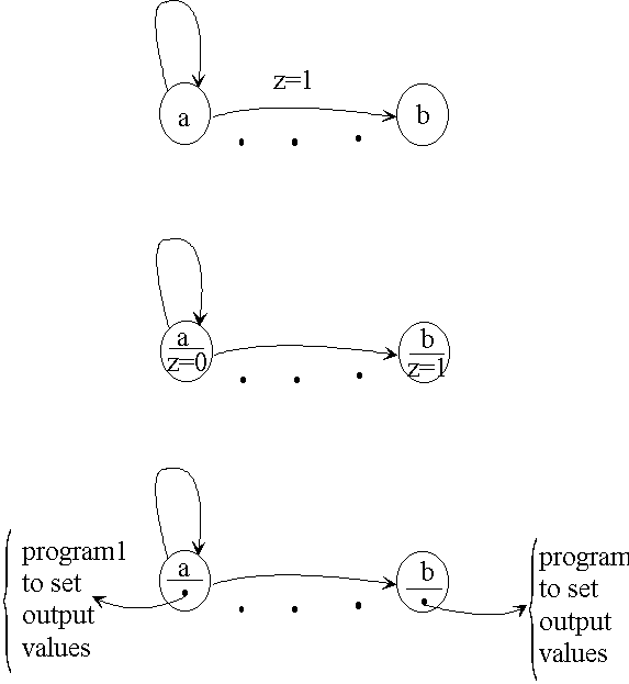
State machines describe general hardware
A simple state machine assigns values to outputs
Synthesizers take state machines with programs with flow instead of simple output values
Can use high level constructs for such programs
Synthesis.state_machines


Can describe state machines with logical and memory parts
Logical part defines sequencing
Memory part updates current state with clock
Synthesis.state_machines
ENTITY detector IS
PORT ( x, clk : IN std_logic; z : OUT std_logic);
END detector;
---
ARCHITECTURE behavioral OF detector IS
TYPE state IS ( reset, got1, got11, got110 );
SIGNAL next_state, current_state : states;
BEGIN
sequencing : PROCESS ( current_state, x )
BEGIN
z <= '0';
CASE current_state IS
WHEN reset =>
IF x = '0' THEN next_state <= reset; ELSE next_state <= got1;
END IF;
WHEN got1 =>
IF x = 0 THEN next_state <= reset; ELSE next_state <= got11;
END IF;
WHEN got11 =>
IF x = 0 THEN next_state <= got110; ELSE next_state <= got11;
END IF;
WHEN got110;
z <= '1';
IF x = 0 THEN next_state <= reset; ELSE next_state <= got1;
END IF;
END CASE;
END PROCESS;
clocking : PROCESS ( clk )
BEGIN
IF ( clk'EVENT AND clk = '0' ) THEN
CURRENT_STATE <= NEXT_STATE;
END IF;
END PROCESS;
END behavioral;
Sequencing PROCESS for logical part
Clocking PROCESS for memory part
Synthesis.state_machines
Hardware design
1. Design state machine
use programs between states
use CASE, IF_THEN, ... for assigning output values
2. Partition into data and control
synthesize data units
synthesize control unit by a state machine
Two design methods both use state machine descriptions
Next two parts will present these methods
Synthesis.conclusions
1. Outline: Introduction, Organization, Outline
2. Review: Levels of abstraction, Entity and Architecture, Signal assignments, Guarded signal assignments, Three state bussing, Process statements, Combinational processes, Sequential processes, Multiplexing, Package
3. MSI Based Design: Use MSI parts of Part 2, Sequential multiplication, Designing the multiplier, Control and data parts, Testing the multiplier
4. General CPU Description: Will present a high level VHDL description of a small CPU. The CPU, Memory organization, Instructions, Addressing, Utilities for VHDL description, Interface, Behavioral description, Coding individual instructions
5. Manual Data_path Design: Will present VHDL description for manual design of data_path. Data components, Bussing structure, Description of logic, Description of registers, Bus resolutions, Component wiring
6. Manual Controller Design: Will present VHDL description for manual design of controller. Controller hardware, VHDL style, Signals and resolutions, State descriptions, Complete CPU, Testing CPU
8. Behavioral_Synthesis: Will present a high level synthesizable CPU description. Synthesis style, Necessary Package, Interface, General Layout, Registers, Clocking, Sequencing, Simulation and Synthesis
9. Dataflow_Synthesis: Will partition the CPU and synthesize each part separately. Synthesis style, Controller, Data components, Data path, Synthesized example, Conclusions
to the top of the document


